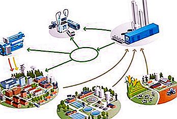
Distribution and transportation of coolant between consumers occurs through a special heating network. It is one of the main elements of the entire structure of engineering communications. The reliability and quality of the transmission directly depend on how it works. Pipelines of heating networks are not the only elements of this structure. In addition to them, it also includes various structures. These, in particular, include throttle and pumping stations, heat points.
Structure
The heat network, based on a centralized supply scheme, is subdivided into two levels in its structure: main and quarter (micro-district). The first consists of elements connecting heat sources with local (district) points of its distribution among end consumers. In most cases, they are a looped system of pipes (diameter 500–1400 mm) and engineering structures. These elements are located throughout the city, which ensures reliable transmission and the ability to satisfy demand for consumption. Thanks to the separation, the operation of heating networks is greatly facilitated. Thus, various control schemes are created that increase the reliability of work and increase the quality of supply. Design and laying of heating networks of the main type are carried out taking into account possible failures in the operation of any underwater element. In this regard, backup links are created. They connect to heat sources. With this approach, a unified management system is created. It is capable of uninterruptedly providing the declared indicators of thermal and hydraulic modes. At the same time, work is carried out even if one of its elements (supplying source, one of the main branches) fails. The distribution of coolant under such conditions occurs more efficiently, losses due to transmission are reduced, fuel economy is observed.

Control
The rules of heating networks provide for the presence of special elements by which the structure is controlled. These, in particular, include locking mechanisms - latches. With their help, the total heating network is divided into separate sections. Impact on the valves allows you to enable (disable) small sections of the line, as well as pump and throttle stations located on them. Most modern appliances are equipped with an electric drive. They are located on average every 1-3 km of the highway. General network management includes monitoring the mode of operation and the state of structural elements, preventing possible malfunctions. To protect against water hammer, a special discharge device is installed at local points.
Quarterly heating network. Features
These structures are branched dead end systems. They are connected to heat points. Management takes place both in manual and offline modes. Such a structure has a diameter of up to 400 mm, in connection with this, interruptions in the supply of thermal energy to consumers as a result of a breakdown of such a network are considered permissible. However, as a result of the general arrangement of supply circuits, in the event of a malfunction only a small part of the end-users suffers. Repair of heating networks in this case does not take much time. Items through which the medium enters the system are automated. This allows you to get savings in the consumption of thermal energy.
Connection to the highway
Distribution networks are connected to the common system using mixers or pumps (mixing and circular), less commonly through water heaters. The use of the latter makes the system more flexible and reliable. This is possible due to the separation of the hydraulic modes of the main and distribution systems. The carrier entering the common networks from different sources may have different temperatures, exceeding that which is already in the pipeline. Supply systems equipped with pumps exclude hydraulic isolation of mains from distribution circuits. As a result, management of the corresponding emergency mode is complicated. In this case, it becomes possible to independently maintain using a pump in distribution networks circular and temperature conditions that will differ from the main ones.
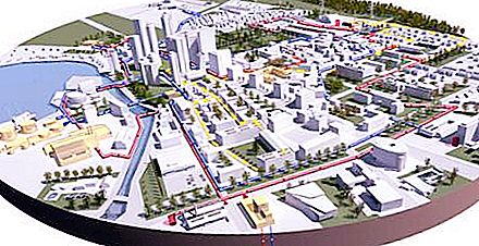
Two-level view of the system
The scheme of the large structure of the heating network has a two-level view. At the top is a ring highway. Branches to heat points of regions depart from it. In the attachment, the ordinary method is used. In the event of a failure in the section of the main to which the heat point is connected, end-users lose thermal energy. Users are connected to the district point using local systems - this is the lower level.
Feed reservation
The heat carrier enters the main network from the CHP and the district boiler house. In this case, it is possible to carry out a backup reservation process in the event of a breakdown of one of the carrier heating points. This is done by installing a jumper on the supply and return lines. The combination of these elements forms a single annular heat network. The projected diameter of the conductive elements of the systems is calculated in such a way as to ensure the throughput of the required medium even in emergency situations. In conditions of stable uninterrupted operation, the coolant moves through all the heat pipes of the network. In this case, the use of jumpers loses its meaning. For more efficient use of jumpers and lower costs for heating the coolant, the "unloaded reserve" method is used. In this case, the jumpers completely overlap. The jumpers are turned on only when the elements of the heating network are broken.
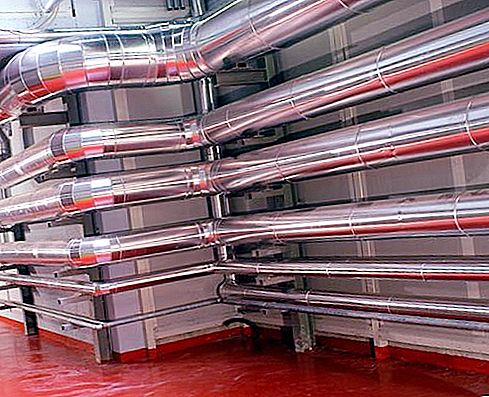
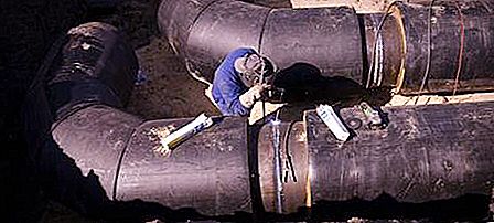
Heat piping networks
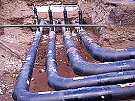
On these elements the carrier is moving, in the form of which water acts. Heat pipes are installed above ground and underground. In the first case, the gasket has a number of significant advantages: increased service life, easy monitoring of the system status, and easier access to troubleshoot. However, the installation of an elevated heat pipe in modern cities is almost impossible due to architectural restrictions. Under these conditions, most systems are underground. To install such pipelines special channels break out.
Use of the system
Before a working start, thermal tests of heating networks are carried out. Installed elements are filled with hot water of different temperatures. The liquid subsequently drains repeatedly during the service life. As a result of all internal influences, the pipe walls change; the way out of this situation is the installation of compensators in the pipelines. The two ends of the plot are fixedly mounted on the supports. In the middle, a compensator is installed. Additionally, the pipelines are fixedly fixed near heat exchangers, pumps. This is done to relieve the load caused by thermal deformation. Supports are placed in channels or special chambers. In the channels, the pipeline is laid on movable supports. In order to constantly monitor the status of the systems, special underground chambers are being constructed. They place various valves, drain valves, air valves and expansion joints. In some cases (for example, with a water supply diameter of more than 500 mm), ground pavilions are erected over the cameras to test heating networks and provide more convenient service. Placement of points and pumping stations takes place in specially equipped buildings.
Choosing the best option for heating networks
Currently, there are a huge number of schemes of heating networks and how to lay them. Therefore, at the design stage, several options are considered. Comparing all possible conditions, they carry out technical and economic calculations, the least costly option with the best characteristics is selected. According to these calculations, the diameter of the elements used, the insulation materials and their thickness, the power of the installed pumps are determined. In addition, the cost of the construction and maintenance of the heat pipe and the heat loss during transmission from the source to the consumer is kept.
")


