One of the multifunctional methods of metal processing is turning. With its help, roughing and finishing are carried out in the process of manufacturing or repairing parts. Optimization of the process and effective quality work is achieved by rational selection of cutting conditions.
Process features
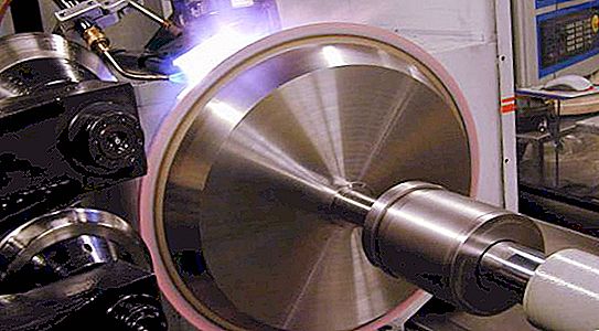
Turning is carried out on special machines using cutters. The main movements are carried out by the spindle, which ensures the rotation of the object fixed on it. The feed movements are made by a tool that is fixed in the caliper.
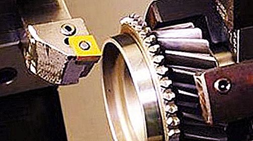
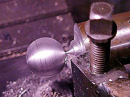
The main types of characteristic work include: face and shaped turning, boring, processing grooves and grooves, trimming and cutting, thread design. Each of them is accompanied by productive movements of the corresponding inventory: continuous and persistent, shaped, boring, cutting, cutting and threaded cutters. A diverse type of machine tools allows you to process small and very large objects, internal and external surfaces, flat and volume workpieces.
The main elements of the modes
The cutting mode during turning is a set of operating parameters of a metal cutting machine, aimed at achieving optimal results. These include the following elements: depth, feed, frequency and spindle speed.
Depth is the thickness of the metal removed by the cutter in one pass (t, mm). Depends on the specified indicators of cleanliness and corresponding roughness. With rough turning, t = 0.5-2 mm, with fine turning - t = 0.1-0.5 mm.
Feed - the distance the tool is moved in the longitudinal, transverse or rectilinear direction relative to one revolution of the workpiece (S, mm / rev). Important parameters for its determination are the geometric and qualitative characteristics of the turning tool.
Spindle speed - the number of revolutions of the main axis to which the workpiece is attached, carried out over a period of time (n, rev / s).
Speed - the width of the passage in one second with the correspondence of a given depth and quality, provided by the frequency (v, m / s).
Turning power is an indicator of power consumption (P, N).
Frequency, speed and power are the most important interconnected elements of the cutting mode during turning, which specify optimization parameters for finishing a particular object and the pace of the entire machine.
Initial data
From the point of view of a systematic approach, the turning process can be considered as the coordinated functioning of the elements of a complex system. These include: lathe, tool, workpiece, human factor. Thus, a list of factors affects the effectiveness of this system. Each of them is taken into account when it is necessary to calculate the cutting mode during turning:
- Parametric characteristics of equipment, its power, type of regulation of spindle rotation (stepwise or stepless).
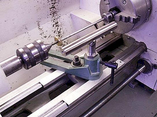
- The method of fastening the workpiece (using the faceplate, faceplate and lunette, two lunette).
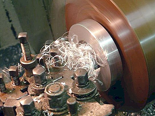
- Physical and mechanical properties of the treated metal. It takes into account its thermal conductivity, hardness and strength, the type of chips produced and the nature of its behavior relative to the inventory.
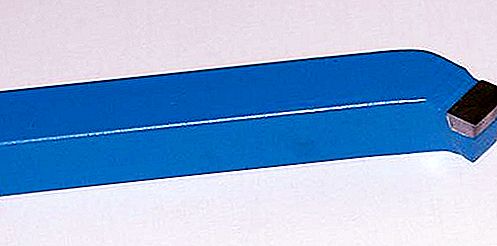
- Geometrical and mechanical features of the cutter: dimensions of the corners, toolholders, radius at the apex, size, type and material of the cutting edge with the corresponding thermal conductivity and heat capacity, impact strength, hardness, strength.
- The given surface parameters, including its roughness and quality.
If all the characteristics of the system are taken into account and rationally calculated, it becomes possible to achieve maximum efficiency of its work.
Turning Efficiency Criteria
Parts made by turning, are most often part of critical mechanisms. The requirements are met taking into account three main criteria. The most important is the maximum performance of each of them.
- Correspondence of materials of the cutter and the turned object.
- Optimization of feed, speed and depth between each other, maximum productivity and quality of finish: minimum roughness, accuracy of shapes, absence of defects.
- The minimum cost of resources.
The procedure for calculating the cutting mode during turning is carried out with high accuracy. There are several different systems for this.
Calculation Methods
As already mentioned, the cutting mode during turning requires taking into account a large number of different factors and parameters. In the process of technology development, numerous scientists have developed several complexes aimed at calculating the optimal elements of cutting conditions for various conditions:
- Mathematical. Implies accurate calculation according to existing empirical formulas.
- Graphanalytical. Combination of mathematical and graphical methods.
- Tabular. The choice of values corresponding to the given working conditions in special complex tables.
- Machine. Using software.
The most suitable is selected by the contractor, depending on the tasks and the mass production process.
Mathematical method
The cutting conditions are analytically calculated during turning. Formulas exist more and less complex. The choice of system is determined by the features and the required accuracy of the miscalculation results and the technology itself.
Depth is calculated as the difference in the thickness of the workpiece before (D) and after (d) processing. For longitudinal work: t = (D - d): 2; and for transverse: t = D - d.
Allowable feed is determined in stages:
- numbers that provide the necessary surface quality, S cher;
- feed taking into account the characteristics of the tool, S p;
- the value of the parameter, taking into account the particular fastening of the part, S det.
Each number is calculated by the corresponding formulas. As the actual feed, choose the smallest of the received S. There is also a generalizing formula that takes into account the geometry of the cutter, the specified requirements for the depth and quality of turning.
- S = (C s * R y * r u): (t x * φ z2), mm / rev;
- where C s is the parametric characteristic of the material;
- R y is the given roughness, microns;
- r u is the radius at the top of the turning tool, mm;
- t x - turning depth, mm;
- φ z is the angle at the tip of the cutter.
The speed parameters of the spindle rotation are calculated according to various dependencies. One of the fundamental:
v = (C v * K v): (T m * t x * S y), m / min, where
- C v is a complex coefficient summarizing the material of the part, cutter, process conditions;
- K v is an additional coefficient characterizing the features of turning;
- T m - tool life, min;
- t x - cutting depth, mm;
- S y - feed, mm / rev.
Under simplified conditions and with the aim of making calculations easier, the speed of turning a workpiece can be determined:
V = (π * D * n): 1000, m / min, where
n is the spindle speed of the machine, rpm
Used power of equipment:
N = (P * v): (60 * 100), kW, where
- where P is the cutting force, N;
- v - speed, m / min.
The given technique is very laborious. There is a wide variety of formulas of varying complexity. Most often, it is difficult to choose the right ones to calculate the cutting conditions during turning. An example of the most universal of them is given here.
Table method
The essence of this option is that the indicators of the elements are in the normative tables in accordance with the source data. There is a list of directories in which feed values are given depending on the parametric characteristics of the tool and the workpiece, the geometry of the cutter, and the specified surface quality indicators. There are separate standards containing the maximum permissible restrictions for various materials. The starting coefficients necessary for calculating the speeds are also contained in special tables.
This technique is used separately or simultaneously with the analytical one. It is convenient and accurate in application for simple serial production of parts, in individual workshops and at home. It allows you to operate with digital values, using a minimum of effort and initial indicators.


